Showing posts with label petroleum conferences. Show all posts

Thursday, August 1, 2019

Innovation R&D | Robotic Drilling System | oil and gas industry

If you are interested in presenting a talk at the conference ( World Congress on Petrochemistry and Chemical Engineering ), please submit a copy of your abstract here Abstract Submission


Robotic Drilling Systems AS (RDS) develops a game-changing drill-floor solution consisting of robotic technology for fully unmanned drill floor operations. The system handles pipe and tools and the technology can be applied both on pipe-deck and drill-floor on all drilling structures (new builds and retrofit) for both land and offshore installations.

The robotic control system ensures seamless, fast and precise work operations between the electric drill floor machines. The benefits are faster drilling operations, high safety level due to unmanned operations, and lower installation, maintenance, and operations costs.

The technology development is supported by the Research Council of Norway, Statoil, Shell, ConocoPhillips, Total, ENI, and Innovasjon Norge.


RDS-Description


RDS is developing a fully electric and robotic drill floor for the fast, seamless and human-free operation of pipe and tools on the drill floor. In order to achieve this, three major innovations had to be brought forward:


  • Electric drill floor machines, such as electric roughneck and electric pipe handler, to allow for precise operation
  • A dynamic robot control system to allow for flexible operations
  • A drill floor robot to replace manual operation

Fig.1-The Robotic System

The system can be used on new-builds or retro-fitted to existing rigs. In order to achieve a seamless system with good motion control, RDS has replaced the conventional hydraulic drill floor machines with a new generation of electrical machines or robots. In addition to avoiding an HPU, the electric system is easier to install and integrate on the rig. As standard electric motors and gear are used, potentially the reliability will be higher and the energy consumption will be significantly lower for electric robots.

Early studies indicate a potential saving of up to 40 rig days per year for a rig (depending on how much of operation time is considered critical), including non-productive time. Several thousands of manual operations will be avoided.

In addition to saved rig time, improved HSE and reduced OPEX, a full robotic system will give other benefits, such as less downtime, faster installation, lower noise, less energy consumption, and less CO2 emission.

RDS is in the process of workshop testing the robotic drill floor system including the seamless co-operation between the machines/robots.

In general industry, robots have been used for decades in the manufacturing process. The oil and gas industry has so far been very conservative.


Related image

Robot-based drilling operations will generate a wealth of process data that can be used to better understand and optimize the drilling process.

The technology not only reduces the personnel costs associated with the rig, but it also redefines the role of the drilling crew. The focus will change from drill floor tasks to the well construction process.

Friday, July 26, 2019

Petroleum Industry | HSE – Concepts | Health - Safety - Environment


If you are interested in presenting a talk at the conference ( World Congress on Petrochemistry and Chemical Engineering ), please submit a copy of your abstract here Abstract Submission


Petroleum industry makes use of many different activities in all the sectors of the business cycle: from upstream to downstream.

Oil and services company’s management apply HSE policies to all levels of operations and in all sectors.

Health, Safety, Environment are separate issues, each with its own technology, but they are often combined in the same functional groups within the oil companies.

These three subjects are of paramount importance to the petroleum industry and adherence to HSE guidelines is a requirement for operators worldwide and is also dictated by internal policies of most corporations.

It is fundamental to have and implement an HSEMS (Health, Safety, and Environmental Management System) which defines the principles by which operations are conducted and control the risks in the whole industry cycle.

Immagine


Health

The health function typically deals with the well-being of the employees as they live and work in their environment.

It deals with the conduct of activities in such a way as to avoid harm to the health of employees and others, and to promote, as appropriate, their health.

Typically, the health function focuses on the effects of oil field chemicals and oil field physical environment on employees.


Safety

The safety function focuses on protecting the employee from the risk involved during any type of operation and duties.

It is related to the principle that all injuries should be prevented and actively promote amongst all those associated with their activities the high standards of safety consciousness and discipline that this principle demands.

The safety function seeks to minimize these risks and monitor the effectiveness of the minimization activities.


Environment


The environmental function focuses on the effects that petroleum activities have on the natural resources.

The environmental issue pursuit the progressive reductions of emissions, effluents, and discharges of waste materials that are known to have a negative impact on the environment, with the ultimate aim of eliminating them.

It aims to provide products and services and advice which will not cause injury or undue effects on the environment.

It promotes the protection of environments which may be affected by the development of petroleum activities and seek continuous improvement in the efficiency of use of natural resources and energy.

All petroleum activities are subject to a declaration of environmental compatibility issued by the competent Authorities after in-depth studies of the possible environmental impact. These studies include

  • Identify sensitive environmental issues
  • State possible environmental impact
  • Provide a description of the technology and methodology necessary to reduce the risk of damage

The declaration of environmental compatibility is then issued on the basis of a synthetic evaluation which is the cornerstone for conclusions on how acceptable the environmental risk is in terms of chemical pollution, noise pollution, visual impact, smells and, more generally, of any other element which may interfere with the environment.

Related image


Oil Companies are constantly researching technology which will allow them to reconcile their operations with the protection of the environment and local ecosystems.

Occupational health and safety issues should be considered as part of a comprehensive hazard or risk assessment, including, for example, a hazard identification study [HAZID], hazard and operability study [HAZOP], or other risk assessment studies.

The results should be used for health and safety management planning, in the design of the facility and safe working systems, and in the preparation and communication of safe working procedures.


The following environmental issues should be considered as part of a comprehensive assessment and management program that addresses project-specific risks and potential impacts:

  • Air emissions
  • Wastewater/effluent discharges
  • Solid and liquid waste management
  • Noise generation
  • Terrestrial impacts and project footprint
  • Spills

During the transport of petroleum, safety and environmental issues are well studied, assessed and continuously implemented to avoid any type of problem which could affect the people involved and the environment which can be very sensitive (land and marine).

The marine transport of oil has increased during the years and the spills are not an occasional consequence of oil traffic.

The environmental impacts of petroleum refinery industry are both direct and indirect:

  • Indirect impacts are connected with the final use of petroleum products and pertain not so much to the environmental management of a refinery, as to its overall configuration and to the integration of the various processes that determine the ecological quality of the products
  • Direct impacts are generated by processing units and by the activities carried out within the refinery.

The industry’s adoption of more stringent restrictions concerning environmental safety does not always mean increased costs in the long-run, but can also provide an opportunity for improving the overall efficiency of productive activity as well as create conditions of greater competitiveness.

Credits: Oil and Gas portal

Tuesday, July 23, 2019

Petroleum - Downstream - Refining Cycles

If you are interested in presenting a talk at the conference ( World Congress on Petrochemistry and Chemical Engineering ), please submit a copy of your abstract here Abstract Submission


SIMPLE CYCLE REFINERIES


Simple cycle refineries (Hydroskimming) are traditionally equipped with crude oil distillation plants, desulphurization units for distillates, and with units to increase the octane number of gasoline.


The hydrogen for hydrodesulfurization is supplied by the reforming units. More recently, the reform units have been accompanied by units for the isomerization of the C5-C6 cut.

Diagram of a Simple Cycle (Hydroskimming) Refinery

Diagram of a Simple Cycle (Hydroskimming) Refinery


THERMAL CONVERSION CYCLE


In addition to the units in the hydroskimming scheme, the thermal conversion cycle also includes visbreaking units (plus thermal cracking) or cokers; these represented the first generation of conversion processes.

Thermal Conversion Cycle with Visbreaking and Thermal Cracking

Thermal Conversion Cycle with Visbreaking and Thermal Cracking


Visbreaking (VB) and coking have always been relatively important, given their ability to treat the residues of distillation atmospheric and vacuum in a relatively simple and economical way. 

Coking, in particular, may also represent the basic process in a deep conversion refinery if a use is found for the coke produced (combustion, sale or gasification). 

Yields, especially in the case of visbreaking, are not high; the same is true of the quality of the products. 

However, there is an increase in middle distillates (in the case of VB) or light products in general (in the case of coking), and this improves the refinery’s operational flexibility.

TCC with coking

Thermal Conversion Cycle with Coking


However, this cycle is unable, at least in its simplest form, to meet the quality and environmental requirements of a modern industrialized country.


CATALYTIC CONVERSION CYCLE


Catalytic conversion refineries are equipped, in addition to the other units, with more traditional conversion plants, especially those for catalytic cracking and/or hydrocracking .

Since the beginning, catalytic cracking has been more popular in the American refining system than in the European. Often, the catalytic cracker is followed by an alkylation plant which uses the gaseous by-products of FCC.

TCC with FCC and alky

Catalytic conversion cycle with FCC and alkylation


Hydrocracking, which necessarily requires the presence of purpose-built plants for the production of hydrogen (steam reforming), became widespread later and represents the basis of many modern refining cycles.

CCC with hydrocraking

Catalytic conversion cycle with hydrocracking


Credits: Oil and Gas portal

Friday, July 19, 2019

Petroleum - DOWNSTREAM

If you are interested in presenting a talk at the conference ( World Congress on Petrochemistry and Chemical Engineering ), please submit a copy of your abstract here Abstract Submission


Fundamentals of Downstream Petroleum

The downstream sector is the refining of petroleum crude oil and the processing and purifying of raw natural gas, as well as the marketing and distribution of products derived from crude oil and natural gas.

The purpose of refining is to transform the various kind of crude oil into finished products that meet certain precise specifications.

FundamentalDWS.jpg


The range and quality of refined petroleum products produced by any given refinery depend on the type of crude oil used as feedstock and on the configuration of the refinery. 

Light and sweet crude oils are more expensive and generate greater yields of higher-value refined petroleum products, such as gasoline, diesel and aviation fuels.

Heavier and sourer crude oil qualities are less expensive and generate greater yields of lower value petroleum products, such as fuel oils.

The configuration of certain refineries is typically oriented towards the production of gasoline whereas the configuration of others is oriented towards the production of middle distillates, such as diesel fuel and aviation fuels.


Crude Oil Refining

Credits: Oil and Gas portal

Wednesday, July 17, 2019

Petroleum Exploration- Geological mapping and prospecting

If you are interested in presenting a talk at the conference ( World Congress on Petrochemistry and Chemical Engineering), please submit a copy of your abstract here Abstract Submission


Geological mapping and prospecting


Geological mapping and prospecting are valuable techniques in petroleum exploration.

Geological prospecting makes use of geological disciplines such as petrography, stratigraphy, sedimentology, structural geology, geochemistry.

Such disciplines are used to achieve different targets but it must be stressed that their integration is fundamental to depict a picture of reality.


Geophysical methods


Geophysical methods allow to study the physical properties of the subsurface rocks and they can be used in different phases of the exploration in order to collect different types of information.

Geophysical methods such as gravimetric, magnetometric, magnetotelluric, seismic are often combined to obtain more accurate and reliable results.


1. Gravimetric prospecting


  • Gravimetric prospecting is a geophysical technique which is able to identify anomalies in the gravity acceleration generated by contrasts in density among bodies in the subsurface.
  • Gravimetric prospecting is used to reconstruct the main structural elements of sedimentary basins such as extension, thickness, salt domes, intrusive plutons, and dislocations or fault lines.

Immagine5

2. Magnetometric prospecting


  • This method involves measuring local anomalies in the Earth’s magnetic fields.
  • The method enables acquisition of data on structural characteristics and depth of the susceptive basement and therefore, indirectly, on the thickness of sedimentary overburden and identifies the presence, depth, and extension of volcanic or plutonic masses within the sedimentary sequences.

Immagine6

3. Seismic prospecting


  • Seismic prospecting has become the most valuable technique to reduce exploration risk of being unsuccessful in locating a prospect.
  • The technique is based on determinations of the time interval that elapses between the initiation of a seismic wave at a selected shop point and the arrival of reflected or refracted impulses at one or more seismic detectors.
  • The phase of seismic data acquisition is followed by the seismic data processing phase (aimed to the alteration of seismic data to suppress noise, enhance the signal and migrate seismic events to the appropriate location in space) than by the interpretation of the generated subsurface image.

Cattura


Left: Onshore seismic survey
Right: Marine seismic survey

Powered by advanced supercomputer power, rapid data loading, high-speed networking, and high-resolution graphics, visualization centers provide the ability to display and manipulate complex volumes of 3D data resulting in better interpretation of more data in less time.


Immagine10

4. Drilling the exploration well


  • Once geological and geophysical information has defined and evaluated (technically and economically) the drillable prospect, it is possible to move to a fundamental phase of the exploration project – the drilling of the first exploratory well.
  • The drilling of the exploration well is aimed to confirm the presence of petroleum accumulation.

Immagine11

5. Well logging


  • The well logging technique consists of lowering a ‘logging tool’ into the well to acquire geological data and to reveal reservoir fluids characteristics.
  • Well logging help geoscientists and engineers to understand:
                         Presence of reservoir
                         Presence of hydrocarbons and characteristics
                         Reservoir properties, etc

6. Well testing


  • A well test is a measurement under controlled conditions of all factors relating to the production of oil, gas, and water from a well.
  • Well tests are conducted to acquire dynamic rate, pressure, temperature, and fluid property data.
  • The acquired information is used to determine reservoir capabilities and important decisions such as production methods, well production equipment, and field development drilling are made from the interpretation of well test results.

Cattura2

Credits: Oil and Gas portal

Tuesday, July 16, 2019

Petroleum Exploration- Upstream

If you are interested in presenting a talk at the conference ( World Congress on Petrochemistry and Chemical Engineering), please submit a copy of your abstract here Abstract Submission


 Petroleum Exploration- Upstream


The role of exploration is to provide the information required to exploit the best opportunities presented in the choice of areas and to manage research operations on the acquired blocks.

An oil company may work for several years on a prospective area before an exploration well is spudded and during this period the geological history of the area is studied and the likelihood of hydrocarbons being present quantified.


Immagine1


                                                            Stages of a typical exploration program


Indeed, exploration is a risk activity and the management of exploration assets and associated operations is a major task for oil companies.

The risk cannot be eliminated entirely but can be controlled and reduced adopting appropriate workflow, conceptual and technological innovations.

Technological development has provided oil companies with Basin Modeling – which is a numerical simulation that allows the temporal reconstruction of the history of a sedimentary basin and the associated evolution of the processes related to the formation of petroleum accumulations.


Immagine2PNG

                                                    Basin modeling – Petroleum system


On the basis of data and evidences collected from the preliminary studies, the company management, in the light of the possibilities and the probabilities of a discovery based on G&G data, aside from considerations of an economic nature, may decide to move to the following stage, which is the acquisition (through direct negotiations or by taking part in bids, etc.) of the legal right to perform prospecting in the selected area/block.

The owner of the mining right is normally the State, with which the oil company stipulates a contract establishing the contracting parties’ rights.

Production Sharing Contracts and service contracts are frequently adopted nowadays.

The sequence of activities covered by an exploration permit is fairly uniform, and include

  • the creation of a database
  • the analysis of available data
  • the programming of mapping and geological and photo-geological surveys
  • seismic surveys and interpretation of seismic data
  • the choice of well locations, drilling
  • the analysis of results and the decision as to whether or not to proceed with the application for a lease or to release the area after fulfilling obligations

Immagine4


                                            The main petroleum exploration techniques

The goal of exploration is to identify and locate a prospect, to quantify the volume of hydrocarbon which might be contained in the potential reservoirs and to evaluate the risk inherent the project itself.

A prospect is a viable target evidenced by geological and geophysical indications that are recommended for drilling an exploration well.


Credits: Oil and Gas portal

Thursday, July 11, 2019

Petroleum- Interesting FACTS #5

The world uses over 36 billion barrels of oil per year


Around the world, people use around 100 million barrels of oil and liquid fuels per day, which adds up to over 36 billion barrels per year. This number has been rising rather than falling over the last decade and may continue to rise despite the increasing popularity of alternative and green energy resources.


Image result for The world uses over 36 billion barrels of oil per year


How many years of oil is left in the world?


We currently consume the equivalent of over 11 billion tonnes of oil from fossil fuels every year. Crude oil reserves are vanishing at a rate of more than 4 billion tonnes a year – so if we carry on as we are, our known oil deposits could run out in just over 53 years.


Related image


What Will Happen If We Run Out of Oil and Petroleum? 


Between 1965 and 2005, humanity has seen an increase in demand for crude oil by about two and a half times. We are using twice as much coal and three times more natural gas. At present, crude oil constitutes around 33% of global energy needs.


Credits: dare-energy.com

Tuesday, July 9, 2019

Petroleum- Interesting FACTS #4

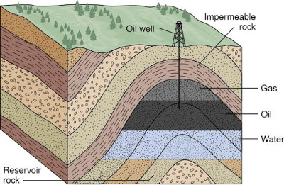
An Oil Reservoir is Not a Giant Underground Pool


Contrary to widespread belief, an oil reservoir is not a giant pool of liquid beneath the ground that can easily be sucked onto the surface. Rather, the oil is trapped in the pore spaces between rock crystals and soil grains.

Think of an oil reservoir as a giant sponge soaked in oil. It all comes down to how oil is formed i.e. the burial, compression, and heating of dead organisms underneath sedimentary rocks over millions of years.

Conventional hydrocarbon reservoirs consist of three main parts: The source rock, the reservoir rock, and the cap rock. 
  • The source rock is the rock that contains the kerogen that the oil and gas forms from. 
  • The reservoir rock is the porous, permeable rock layer or layers that hold the oil and gas. 
  • The cap rock seals the top and sides so that the hydrocarbons are trapped in the reservoir, while water often seals the bottom.


Conventional hydrocarbon reservoirs

Reservoir rocks need to be both porous and permeable. This means that there are small pockets of space within the rock where oil or gas can settle and small channels connecting these pockets to allow the oil or gas to flow out of this rock easily when it is drilled. These spaces between grains can develop as the formation of rock occurs or afterward, usually as a result of groundwater passing through the rock and dissolving some of the cement between sediment grains.

Credits: energyeducation.ca

Wednesday, July 3, 2019

Petroleum- Interesting FACTS #2

It is standard practice that gasoline is stored in red containers; diesel is stored in yellow containers; kerosene is stored in blue cans and oil combustibles are stored in green containers.


It is vitally important to the safe operation of our business to keep fuels stored properly and easily identified. The safe handling of flammables and combustibles requires you to provide training and safety rules which include having the proper fuel storage containers on hand.


Gasoline, kerosene, diesel and certain combustible oils are the most common fuels used in businesses. To be safe, the need for several different fuel storage container types and sizes are used. The fuel storage containers are made of top quality material.

Color-Coded Containers

When working around several different types of fuels and other fluids, it is important to keep them contained and stored so that you will always know which chemicals are in which fuel storage container. Color coding helps immensely. 


Related image


To find additional information as look at each of the product lines but, in general: 

1.  Gasoline is stored in Red containers; 

2.  Diesel is stored in Yellow containers; 

3.  Kerosene is stored in Blue cans and 

4.  Oil combustibles are stored in Green containers.

Friday, June 7, 2019

Oil & Gas- Drilling Technologies

Oil well drilling is a complex operation and the drilling industry engages the services of personnel and a complicated array of machinery and materials to drill an oil/gas well to depths greater than 6000 meters, The drilling industry has seen technological progress, however, these advances have not changed the fact that, besides the use of complicated machinery, successful drilling is a result of tremendous team effort. Numerous personnel from the operating company and several service companies work together to drill and complete an oil/gas well. A drilling rig is used to drill a hole, and this requires qualified personnel, different types of equipment the application of a great variety of techniques.


When a drilling project is commenced, two goals must be achieved:

  • To drill and finish the well in a safe manner (personal injuries, technical problems) and according to its purpose;
  • To complete the project with minimum cost.

The overall costs of the well must be optimized and this optimization may influence where the well is drilled (onshore – extended reach or offshore above reservoir), the drilling technology applied (conventional or slim-hole drilling), as well as the evaluation procedures, run to gather subsurface information for future drilling projects. Rotary drilling is the most efficient technology applied in the oil and gas industry. It is a drilling technology that relies on the continuous circular rotation of the bit to break rocks, while drilling fluids circulate through the bit and up the wellbore to the surface, making it possible to drill safely and efficiently the well.


Rotary drilling rig


The drilling rig consists of a set of equipment and machinery located on the so-called drilling site and normally the rig is not owned by the oil company but by drilling service companies, which hire out the rig complete with operators and which construct the well according to the client’s specifications.


drilling system


Drilling Rig Systems


A drilling rig is composed of different systems:

1. The hosting system

  • It the set of equipment necessary for handling any material inside the well(drill string and the casing);
  • It consists of a structural part (Derrick/mast and substructure), the complex of the crown and traveling block, the draw works (hoist) and the drilling line;
  • The substructure is the supporting base for the derrick, the draw works, and the rotary table, and constitutes the working floor for operations, or drilling floor.

hosting system

The Hosting System


2. The rotating system

  • The rotating system allows the rotation of the drill string, and it consists of the rotary table, the Kelly, and the swivel;
  • In modern rigs, top drive groups together the functions of the above three items of equipment.

   
                     kelly system                             top drive

The Kelly System                                                               The Top Drive System

3. The circulation system

  • The circulation system consists of mud pumps, distribution lines, and the mud cleaning and accumulation system;
  • It is the closed hydraulic circuit which allows the mud to flow from the surface to the bottom of the hole, inside the drill string, and subsequently back to the surface, in the drill string borehole annulus;
  • The mud from the hole has to have the cuttings removed before being reinjected to the bottom of the hole and the mud pumps supply the energy necessary for circulation;

Drilling fluids are subdivided into three major classes:

  1. Water-based muds;
  2. Oil-based muds;
  3. Air-based muds (used to reduce bottom hole pressure, to avoid circulation losses in surface layers, or to limit damage to productive formations).

The circulation system


The Circulating System

4.  The power generation system

  • A power generation system is needed to run the machines driving the main components of the rig and it is provided by diesel engines, diesel-electric engines;
  • Power is transferred from the engines to the different rig systems by belts, chains, and driveshafts on a mechanical rig, or by generated DC electrical power on an electric rig and it is distributed to the rotary table and mud pumps and to the draw works.


Drilling rig power


Drilling Rig Power Generation System


5.  The drill string


The drill string is an assemblage of hollow pipes of circular section, extending from the surface to the bottom of the hole.

It has three functions:

  • it takes the drilling bit to the bottom of the hole while transmitting its rotation and its vertical load to it;
  • it permits the circulation of the drilling fluid to the bottom of the hole;
  • it guides and controls the trajectory of the hole.


Immagine11       Immagine12             Immagine13

 Drill String                                   An Insert Tricone                                           Bit A PDC Bit

6.  Casing

  • The casing is a steel tube that starts from the surface and goes down to the bottom of the hole and is rigidly connected to the rocky formation using cement slurry, which also guarantees hydraulic insulation.
  • The casing supports the walls of the hole and prevents the migration of fluids from layers at high pressure to ones at low pressure.


Immagine14

Casing Strings

7.  Cementing


Cementing is the operation of pumping a cement slurry between the casing and the formation, and can be performed by injection into the annulus from inside the casing.

The cementing (primary cementing) serves to rigidly connect the casing to the formation and to guarantee the hydraulic insulation of the various formations, preventing the migration of the fluids from layers at high pore pressure to those at low pressure.

The centralization of the casing is particularly important, as the geometry of the well is seldom regular, but tortuous and with a variable diameter.

Immagine15


Primary cementing

Credits: Oil and Gas portal

Thursday, June 6, 2019

INTRODUCTION TO OIL & GAS WELL DRILLING

The term drilling indicates the whole complex of operations necessary to construct wells of the circular section applying excavation techniques.


To drill a well it is necessary to carry out simultaneously the following actions (drilling process):
  • to overcome the resistance of the rock, crushing it into small particles measuring just a few mm;
  • to remove the rock particles, while still acting on fresh material;
  • to maintain the stability of the walls of the hole;
  • to prevent the fluids contained in the drilled formations from entering the well.
This can be achieved by using rotary drilling rigs which are the ones operating today in the field of hydrocarbons exploration and production.

The drilling rigs are complexes of mobile equipment which can be moved (onshore and offshore) from one drill site to another, drilling a series of wells.

In rotary drilling, the rock is bored using a cutting tool called the bit, which is rotated and simultaneously forced against the rock at the bottom of the hole by a drill string consisting of hollow steel pipes of circular section screwed together.


Immagine1

                      Land Drilling Rig


After having drilled a certain length of the hole, in order to guarantee its stability it has to be cased with steel pipes, called casings, joined together by threaded sleeves.

The space between the casing and the hole is then filled with a cement slurry to ensure a hydraulic and mechanical seal.

The final depth of the well is accomplished by drilling holes of decreasing diameter, successively protected by casings, likewise of decreasing diameter, producing a structure made up of concentric tubular elements.


Image result for oil drilling process animation

The Drilling Process

Planning the drilling of a well


The planning of a well is a fundamental part of the drilling process – it is the basis for making all the important technical choices, for assessing the costs and organizing the actual construction of the well in the most efficient way.

The well planning starts the moment when the interpretation of the seismic data and the reconstruction of the geology of the area reveal the presence of a structure favorable to the accumulation of hydrocarbons.


Immagine3

Overview of the well planning process


Choice of the rig, wellhead, and BOP


The casing levels, the diameters, and weight of the strings, the pressures and temperatures concerned, and the volumes of drilling mud to be used, are all aspects participating in determining the choice of rig type, blowout prevention systems (BOP, choke manifold, hydraulic circuit) and wellheads.

The choice of the rig is closely bound up with the depth it is wished to reach and with the weight of the strings concerned.

According to the weights of the strings to be handled, rigs are used that have different characteristics, and what is of basic importance is the strength of the whole assembly, (traveling block, crown block, hook and derrick floor) from which the string hangs while being lowered into the well.

In the offshore activity, the choice of the rig is determined, not only by the weight of the strings but also by the depth of the water in the area of operations.

Drilling rigs installed on offshore vessels or platforms are built to reach the maximum possible depths and have all the material and equipment necessary for drilling on board.

The composition of the wellhead depends on the pressures that can be reached during the various working phases – both drilling and production – and on the diameters of the strings to be lowered into the well.


Well abandonment


If, when drilling has been completed, the well is productive hydrocarbons, a start is made on all those operations that will ensure its economically advantageous working, whereas if, on the contrary, it should prove to be barren or in any case not economically exploitable, it will be shut down.

Well shutdown entails the restoring of the initial conditions of the section of the well not lined and possibly also the lined part if the separation of the permeable levels of different pressure is not assured.

The purpose of these measures is to prevent the transfer of fluids from one level to the other.

The final shutdown of a well must satisfy not only the requirements set out in the engineering best practices fixed by the operator but must also respond to all the requisites of law aimed at safeguarding the environment and the safety of the people living in the vicinity of abandoned wells.


Immagine6

Well Plug & Abandonment

Tuesday, June 4, 2019

Fundamental of Reservoir Simulation

Reservoir simulation is an area of reservoir engineering that, combining physics, mathematics, and computer programming to a reservoir model that allows the analysis and prediction of the fluid behavior in the reservoir over time.

It can be simply considered as the process of mimicking the behavior of fluid flow in a
petroleum reservoir system ( including reservoir rock and fluids, aquifer, surface, and subsurface facilities) through the use of either physical or mathematical models.

It’s a valuable tool to understand the oil and gas reservoir performance under various operating strategies.


Basically, reservoir simulation consists of:

1.   a geological model in the form of a volumetric grid with cell/face properties that describe the given porous rock formation
2.   a flow model that describes how fluids flow in a porous medium, typically given as a set of partial differential equations expressing conservation of mass or volumes together with appropriate closure relations
3.   a well model that describes the flow in and out of the reservoir, including a model for flow within the well bore and any coupling to flow control devices or surface facilities


flowchart

 Steps to undertake during a Simulation study


Reservoir simulation is used for two main purposes:

  • to optimize development plans for new fields
  • to assist with operational and investment decisions.

To carry out reservoir simulation, it is necessary to perform several and complex studies that are normally made by teams of specialists from different disciplines – due to a large amount of data required for the preparation of the simulation input data set.


The main elements of a simulation study include
  • matching field history
  • making predictions (including a forecast based on the existing operating strategy)
  • evaluating alternative operating scenarios

Numerical techniques and approaches

Traditional finite difference simulators dominate both theoretical and practical work in reservoir simulation. Conventional Fluid Dynamics (FD) simulation is underpinned by three physical concepts: conservation of mass, isothermal fluid phase behavior, and the Darcy approximation of fluid flow through porous media. Thermal simulators (most commonly used for heavy crude oil applications) add conservation of energy to this list, allowing temperatures to change within the reservoir.


Numerical techniques and approaches that are common in modern simulators:

  • Most modern FD simulation programs allow for the construction of 3-D representations for use in either full-field or single-well models.2-D approximations are also used in various conceptual models, such as cross-sections and 2-D radial grid models.
  • Theoretically, finite difference models permit discretization of the reservoir using both structured and more complex unstructured grids to accurately represent the geometry of the reservoir. Local grid refinements are also a feature provided by many simulators to more accurately represent the near wellbore multi-phase flow effects. This “refined meshing” near wellbores is extremely important when analyzing issues such as water and gas coming in reservoirs.
  • Representation of faults and their transmissibilities are advanced features provided in many simulators. In these models, inter-cell flow transmissibilities must be computed for non-adjacent layers outside of conventional neighbor-to-neighbor connections.
  • Natural fracture simulation (known as dual-porosity and dual-permeability) is an advanced feature that model hydrocarbons in tight matrix blocks. Flow occurs from the tight matrix blocks to the more permeable fracture networks that surround the blocks, and to the wells.
  • A black oil simulator does not consider changes in the composition of the hydrocarbons as the field is produced. The compositional model is a more complex model, where the PVT properties of oil and gas phases have been fitted to an equation of state (EOS), as a mixture of components. The simulator then uses the fitted EOS equation to dynamically track the movement of both phases and components in the field.


Cattura1


The simulation model computes the saturation change of three phases (oil, water, and gas) and the pressure of each phase in each cell at each time step. As a result of declining pressure as in a reservoir depletion study, gas will be liberated from the oil. If pressures increase as a result of water or gas injection, the gas is re-dissolved into the oil phase.
A simulation project of a developed field usually requires “history matching” where historical field production and pressures are compared to calculated values. The model’s parameters are adjusted until a reasonable match is achieved on a field basis and usually for all wells. Commonly, producing water cuts or water-oil ratios and gas-oil ratios are matched.

Credits: Oil and Gas portal

Monday, June 3, 2019

Petroleum Production Optimization Innovations- Through Tubing Drilling and Completion

Through-tubing drilling and completion is a cost-effective technology for increasing production and recovery. TTDC is a generic term for drilling sidetracks in existing producers and injectors and covers both coiled tubing drilling (CTD) and through-tubing rotational drilling (TTRD), including installing the associated lower completion, typically liners or screens.

The main advantage of the technology is that new reservoir sections can be reached without having to remove the existing, the completion of the production casing, thereby reducing operational time significantly compared to a “standard” slot recovery or side-track. TTDC- wells are particularly useful for accessing pockets of isolated oil and gas in mature fields. Due to the deep side-tracks achieved with this technique, it is possible to minimize borehole lengths and avoid drilling problems in overlying formations.


Image result for Through tubing rotary drilling

Through tubing rotary drilling


WELL MATRIX STIMULATION WITHOUT HCl


Well acidizing is a common practices in the oil industry and hydrochloric acid (HCl) has been used as the main acid for limestone stimulation purposes There are several concerns with the use of HCl acids: health and safety of the field crew, corrosive nature of the acids for the flow lines and equipment, and environmental effects of the produced HCl.

A new product called FF-01 is an environmentally-friendly and equipment-friendly product. It is a conversion to an organic base to maintain very low pH as a vehicle for aggressiveness, along with the creation of buffers and surface tension relievers. Low pH, slower reaction rates with limestone, a small amount of residue after a reaction, safety, minimum damage to equipment, and longevity are the properties of this product. 
Tests have been conducted to develop this new product and study possible improvements in this blend. It has been observed that FF-01 dissolves limestone rock samples with smaller reaction constants compared to HCl However, it will dissolve the same mass of rock if enough time is given, and it lasts longer during the course of reaction while leaving fewer residues. 
HCl performs better in cleaning the near-wellbore rock while FF-01 performs better in generating long wormholes and higher effective permeability compared to the cores that were treated using HCl.

UNCONVENTIONAL STIMULATION


The acoustic stimulation technology has the potential to provide a low-cost procedure for enhancing oil recovery in mature fields. Low-frequency shock waves produced downhole can increase the oil production and are currently producing well with high WC mobilizing immobile oil in ¾ mile range. Application of this technology well suits well/field having the following properties:
  • Oil Viscosity less than 10 cP
  • High water cut, ideally greater than 80%
  • Low GOR, ~10 m3 per m3 of fluid produced is ideal
  • Minimum spacing of 400 m between source wells with production wells spaced within 300 m radius “stimulation zone”, if multiple tools are run.

fig.2innovation

Credits: Oil and Gas portal

Friday, May 31, 2019

Software's used for Petroleum production optimization

Computer Simulations software provides geoscientists and engineers with insights into the behavior of the well under changing conditions. The simulations have moved on from their ‘run’ on time-consuming and expensive supercomputers to faster and cost-effective intelligent platforms. 

New systems provide more accurate results, a better understanding of extractable reserves enabling timely reactions to ever-changing market conditions and significantly lower total cost. The IPM suite Integrated Production Modelling – is developed by Petroleum Experts (Petex). IPM model is an oil or gas production system which includes reservoir, wells and the surface network.


fig.1software


Open Server Communication


IPM allows the integration with the reservoir simulation models – Eclipse, VIP, etc. to evaluate the impact on production. PIPESIM- SCHLUMBERGER  is a flow simulator that can create well models to help increase production and understand reservoir potential. PIPESIM simulator models multiphase flow from the reservoir to the wellhead and considers artificial lift systems, including rod pumps, ESP, and gas lift. PIPESIM enables to

(i)   design optimal well completions and artificial lift systems;
(ii)  diagnose problems that are limiting well production potential;
(iii) optimize production from existing wells by quantifying actions to increase flow rates.


fig.3 software


SAND MANAGEMENT SOFTWARE – SCHLUMBERGER

Sand CADE is a gravel-pack design and evaluation software. Sand CADE software performs engineering calculations to assess the sand control treatment design and supports job execution and evaluation for open-hole and cased-hole gravel-pack completions.
Sand Advisor Software supports screen and gravel selection in open-hole applications by analyzing the formation of particle-size distributions.

Credits: Oil and Gas portal

Innovation R&D | Robotic Drilling System | oil and gas industry

If you are interested in presenting a talk at the conference ( World Congress on Petrochemistry and Chemical Engineering ), please submit ...